Product
Product Overview / H₂S Removal System
H₂S Removal System
1. desulfurization technology
Anyang Bakdal Sewage Treatment Facility desulfurization system (1,540 m³/hr)

Uijeongbu Waste Resource Recovery Facility desulfurization system (310 m³/min)
Hyosung Corporation, Ulsan Plant desulfurization system (6,850 m³/hr)
1-1. Overwiew of desulfurization technology
Jumunjin Agro-Industrial Complex Final Wastewater Treatment Plant (670 m³/min)
Biogas is generated during anaerobic digestion by methanogenic bacteria of organic waste resources that can cause environmental pollution, such as sewage sludge, livestock manure, and food waste. This gas typically contains hydrogen sulfide in the range of 500–7,000ppm.
Landfill Gas (LFG)
Gas released during the anaerobic decomposition of organic components contained in landfilled waste. Hydrogen sulfide concentrations typically range from 5 to 18,000 ppm.
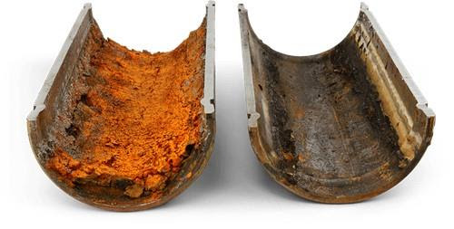
Effects of Hydrogen Sulfide Corrosion of piping and equipment
- Hydrogen sulfide is a highly corrosive gas that attacks key components of high-value power generation facilities, such as pistons, turbines, and piping, leading to reduced system efficiency and severe equipment damage.
- It is a major cause of unplanned shutdowns in power generation facilities.
- When released to the atmosphere, it can cause serious respiratory injury; prolonged exposure to concentrations above 500ppm is life-threatening.
- H₂S is also a precursor of sulfur oxides (SOx), a regulated air pollutant under the Capital Area total air pollution load management system.
- Legal emission standards
- H₂S (hydrogen sulfide)-------->(combustion) SOx (SO₂, SO₃)
- Subject to legal emission limits for sulfur dioxide (SO₂) from air emission facilities
|
|
|
|---|---|
|
annual average limit
|
0.02 ppm
|
|
24-hour average limit
|
0.05 ppm
|
|
1-hour average limit
|
0.15 ppm
|

SOx Emissions from Air Discharge Facilities
2. desulfurization technology
liquid-phase catalytic reaction mechanism
|
|
|
|---|---|
|
Absorption Step
|
Components absorbed into the liquid phase are ionized and exist as individual ions, and the distribution of these ions depends on pH.
|
|
H₂S(gas) + H₂O → H₂S(aq) + H₂O
|
|
|
|
|
|---|---|
|
Ionization Step
|
Hydrogen sulfide dissociates in aqueous solution.
|
|
H₂S(aq) → H⁺ + HS⁻ K₁ = 6.3 × 10⁻⁸ (at 25℃)
HS⁻ → H⁺ + S²⁻ K₂ = 1.3 × 10⁻¹² (at 25℃) |
|
|
|
|
|---|---|
|
Reaction Step
|
Ions in the aqueous phase undergo oxidation through electron transfer with the trivalent iron catalyst and precipitate as elemental (solid) sulfur. The reduced iron is converted to the ferrous (Fe²⁺) form, and is then re-oxidized to ferric iron (Fe³⁺) through a regeneration step.
|
|
HS⁻ + OH⁻ + Fe³⁺–chelate → S⁰ + H₂O + Fe²⁺–chelate
S²⁻ + 2H⁺ + 2OH⁻ + 2Fe³⁺–chelate → S⁰ + 2H₂O + 2Fe²⁺–chelate The reaction between the catalyst and hydrogen sulfide is inferred to proceed as follows: H₂S + Fe³⁺(OH⁻)Ln⁻ → Fe³⁺(SH⁻)Ln⁻ + H₂O Fe³⁺(SH⁻)Ln⁻ → Fe²⁺Ln⁻ + HS⁰ HS⁰ + Fe³⁺(OH⁻)Ln → Fe³⁺Ln⁻ + S⁰ + H₂O Regeneration reaction of the liquid-phase catalyst: O₂(g) → O₂(aq) 4Fe²⁺–chelate + O₂(aq) + 2H₂O → 4Fe³⁺–chelate + 4OH⁻ |
|
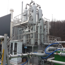
System configuration
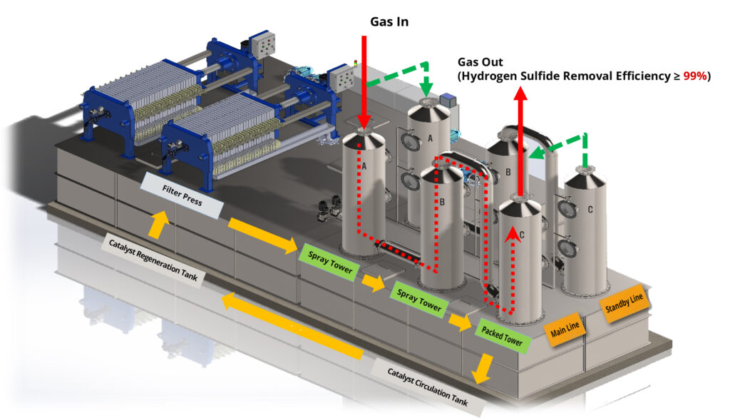
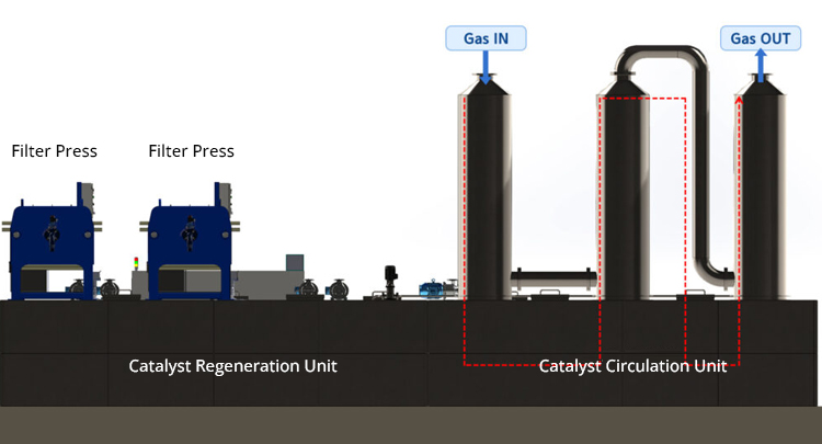
To mitigate piping corrosion caused by hydrogen sulfide, the system is configured as follows
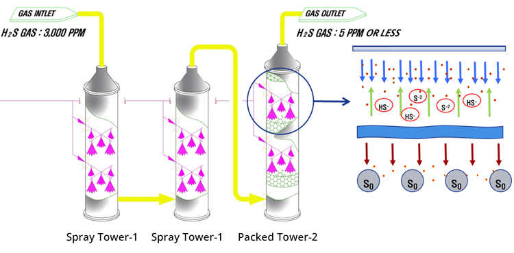
1. Primary and secondary removal of hydrogen sulfide in spray towers 1 and 2
2. Final polishing of residual hydrogen sulfide in the packed tower
3. Discharge of the generated solid sulfur to the outside via a filter press
4. Regeneration of the liquid-phase catalyst that has reacted with hydrogen sulfide by air oxidation
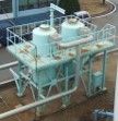
Reactor Configuration
3. Comparison of Desulfurization Technologies
* Design basis: gas flow rate 20,000m³/day (H₂S inlet concentration 2,000ppm, outlet concentration 30ppm)
|
criteria
|
Iron-chelate liquid-phase catalytic process BNE Tech Co., Ltd.
|
Wet catalytic oxidation process
|
Wet chemical scrubber tower
|
Ion exchange process
|
Dry desulfurization tower
|
|---|---|---|---|---|---|
|
Hydrogen sulfide is reacted with oxygen in an iron-chelate catalyst solution and precipitated as elemental sulfur for discharge.
|
Hydrogen sulfide is converted to elemental sulfur through redox reactions catalyzed by an Fe/MgO catalyst.
|
Hydrogen sulfide is removed through a chemical reaction with sodium hydroxide (NaOH).
|
Hydrogen sulfide is removed by dispersing sodium hydroxide (NaOH) in ion-exchange resin cartridges.
|
Hydrogen sulfide is removed by a contact reaction with iron oxide (Fe₂O₃), forming iron sulfate.
|
|
|
Desulfurization catalyst type
|
Liquid-phase catalyst (iron chelate)
|
Liquid-phase catalyst (iron chelate)
|
40% NaOH
|
5~10% NaOH
|
Solid iron oxide (Fe₂O₃)
|
|
Desulfurization catalyst service life
|
Semi-permanent use (regenerated and reused)
|
Consumable (requires periodic chemical dosing)
|
Consumable (requires periodic chemical dosing)
|
Consumable (requires periodic chemical dosing)
|
Replaceable (requires periodic replacement)
|
|
Desulfurization catalyst usage method
|
Reaction by direct circulation of the liquid-phase catalyst
|
Used by dissolving the powder catalyst in scrubbing water
|
Diluted with scrubbing water and recirculated
|
Diluted with scrubbing water and recirculated
|
Removed through contact reaction with the desulfurizing agent
|
|
Operating desulfurization capacity
|
20,000m³/day
|
20,000m³/day
|
20,000m³/day
|
20,000m³/day
|
20,000m³/day
|
|
Required installation area
|
80㎡
(L 8m×W 10m×H10m)
|
176㎡
(L 8m×W22m×H10m)
|
72㎡
(L 8m×W9m×H15m)
|
64㎡
(L 8m×W8m×H15m)
|
56㎡
(L 8m×W7m×H10m)
|
|
Required installation area
|
99% or more
|
95% or more
|
90% or more
|
90% or more
|
70% or more
|
|
Treatment of spent desulfurization waste
|
Separated solid sulfur is dewatered using an in-house filter press and then discharged as waste.
※The solid sulfur is classified as general waste at the plant.
|
Waste sludge (catalyst + solid sulfur) is sent to the central dewatering line, dewatered, and then disposed of.
|
Consigned for treatment as wastewater (designated waste)
|
Consigned for treatment as wastewater (designated waste)
|
Spent desulfurizing agent consigned for off-site treatment (designated waste)
|
|
advantages
|
-High H₂S removal efficiency
-requires minimal installation space and simple system configuration -Catalyst service life is semi-permanent. -Low operation and maintenance cost. -Excellent chemical treatment performance. -No generation of secondary waste. |
-High H₂S removal efficiency
-Only partial removal of odor |
-Stable treatment performance with high H₂S removal efficiency
-Scrubbing function in the desulfurization tower enables partial removal of fine dust and odors |
-Stable treatment performance with high H₂S removal efficiency
-Scrubbing function in the desulfurization tower enables partial removal of fine dust and odors |
-Simple structure and easy maintenance
-Low initial capital cost |
|
disadvantages
|
--Additional labor is required to handle solid sulfur sludge after filter press operation.
-High initial capital expenditure for equipment purchase. |
-Complex system with a large installation footprint; requires periodic chemical dosing and generates wastewater
-Manual handling of powder catalyst causes catalyst dusting and reaction delays (two boxes of material required per charge) -Powder catalyst dust requires installation of an expensive dust collection system -Severe abrasion of mono pumps and other equipment due to Fe/MgO, leading to increased operation and maintenance costs. |
-Periodic chemical dosing required (operator-dependent technology)
-Caustic filtration uses sodium hydroxide and requires back-extraction facilities, resulting in secondary treatment facilities and additional O&M costs -Increased influent wastewater flow leads to higher O&M costs -Difficult to control hydrogen sulfide in the downstream section |
-Requires periodic chemical dosing
-Removal of collected waste generates strong odors -Requires periodic replacement of desulfurizing agent -High load for treating high-concentration hydrogen sulfide -Dehumidification equipment is essential |
|
inlet air flow : 20,000/day, inlet hydrogen sulfide concentration : 2,000ppm, outlet concentration(guaranteed) : 5ppm or less
|
cost category
|
Iron-chelate liquid catalytic process
|
Wet catalytic oxidation process
|
Wet chemical scrubbing(Sodium hydroxide)
|
Ion-exchange resin process
|
Dry desulfurization tower
|
|---|---|---|---|---|---|
|
KRW860,000,000
|
KRW840,000,000
|
KRW7,200,000,000
|
KRW800,000,000
|
KRW680,000,000
|
|
|
KRW28,841,900/year
|
KRW77,672,000 /year
|
KRW76,650,000 /year
|
KRW59,130,000 /year
|
KRW99,280,000 /year
|
|
|
other related cost
|
KRW17,827,900 /year
|
KRW37,102,260 /year
|
KRW46,985,000 /year
|
KRW46,985,000 /year
|
KRW20,705,000 /year
|
|
maintenance cost
|
KRW45,841,900
|
KRW114,774,260
|
KRW123,635,000
|
KRW81,594,300
|
KRW119,985,000
|
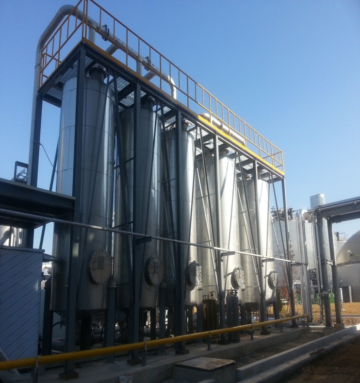
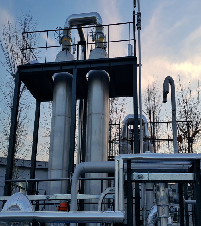
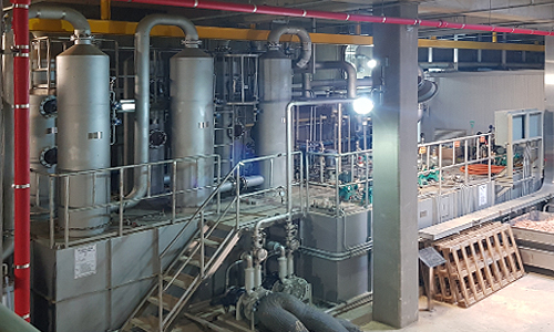
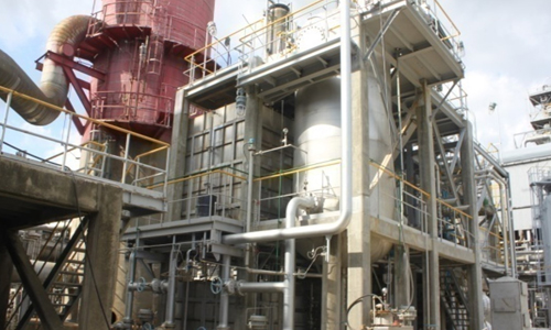
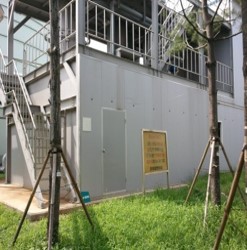
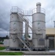
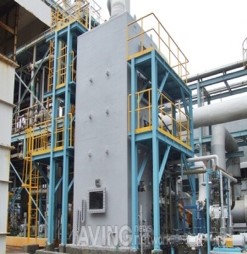
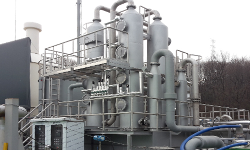
photos of our installed equipment
advantages of applying liquid catalytic desulfurization technology
|
evaluation criteria
|
advantages
|
|---|---|
|
economic feasibility
|
• Enables semi-permanent use of the catalyst
• Reduces waste disposal costs |
|
operational stability
|
• Easy pH control with a small amount of stabilizer
• Stable regeneration reaction extends catalyst life • High removal efficiency is maintained consistently over the long term |
|
environmental performance
|
• Enables reuse of the liquid catalyst
• Does not generate secondary environmental pollutants from chemical reactions • Allows recycling of recovered sulfur |
|
field applicability and maintainability
|
• Applicable regardless of inlet concentration
• Easy to respond to concentration fluctuations • Easy operation • Convenient quality control and installation |

4. Siloxane Removal Technology
- Siloxane Removal System
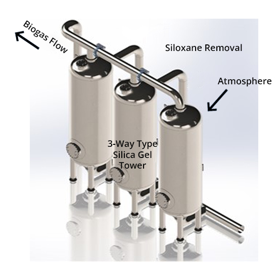
Siloxane removal unit design
- To effectively remove linear siloxanes (L2, L3) and cyclic siloxanes (D4, D5), the upper section of the adsorption tower is filled with activated carbon and the lower section with silica gel.
- As activated carbon cannot be regenerated and has a short service life, an adsorbent inlet and discharge port are provided for easy replacement.
- A 2-way tower configuration is adopted, with one tower in removal operation and the other in regeneration mode.
- When using regenerable silica gel, a hot-air supply unit for thermal regeneration is installed.